


| SPECIFICATION OF PRODUCT |
| DESCRIPTION | : | DC FAN |
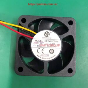
| MODEL | : | DFB401005M |
| DIMENSIONS | : | 40X40X10 |
| BEARING TYPE | : | Ball Bearing |
| RATED VOLTAGE | : | DC5V |
| OPERATING VOLTAGE | : | DC 3.5-5.75V |
| START-UP VOLTAGE | : | DC 3.5V(ON/OFF) |
| RATED CURRENT | : | 180mA(Max220mA) |
| LOCKED CURRENT | : | ≤50mA |
| RATED SPEED | : | 7500RPM±10%(25℃) |
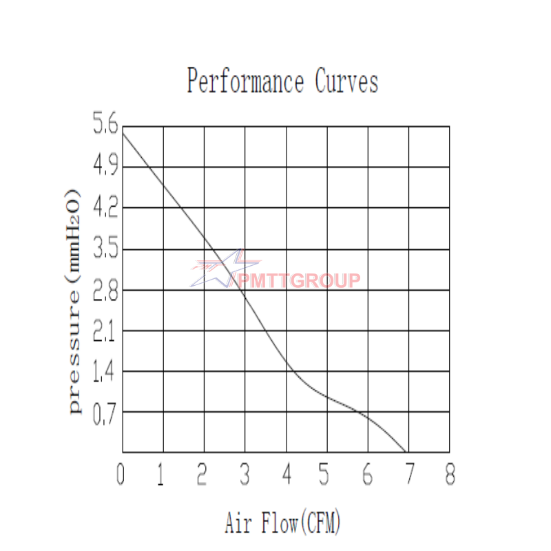
| AIR FLOW | : | 6.9CFM |
| AIR PRESURE | : | 5.4mmH2O |
| NOISE LEVEL | : | 35.8dB(A) |
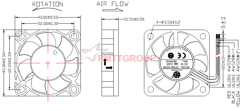
| CONNECTION LEAD TYPE | : | UL1061 28#AWG outside the frame=100mm
Red (positive pole), |
| LABEL | : | DFB401005M DC 5V—0.20A |
1.0. SCOPE
This documentation defines the thermal, mechanical & electrical characteristics of DC FAN DFB401005M
2.0. MATERIAL
2.1. Frame : PBT OF UL94 V-0
2.2. Impeller: PBT OF UL94 V-0
2.3. Bearing type: Two Ball Bearing
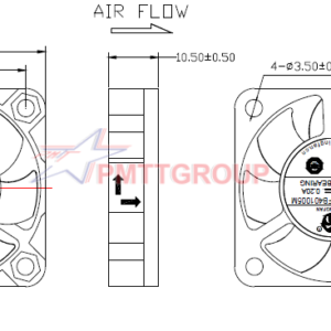
3.0. DIMENSIONS & CONSTRUCTION
All dimensions, direction of rotation and air flow were specified as per drawing attached.
4.0. CHARACTERISTIC & DEFINITION
4.1. All rated characteristics were specified as per data sheet enclosed
4.2. Rated Current: Rated Current shall be measured after 3 minutes of continuos rotation at rated voltage.
4.3. Rated Speed: Rated Speed shall be measured after 3 minutes of continuos rotation at rated voltage.
4.4. Start Voltage: The voltage which is able to start the fan to operate by suddenly switching “ON”
4.5. Input Power: Input Power shall be measured after 3 minutes of continuos rotation at rated volage.
4.6. The fan can be locked, Locked Rotor Current: Locked Current shall be measured within one minute of rotor Locked after 3 minutes of continuous at rated voltage in clean air.
4.7. Air Flow & Static Pressure: The air flow data and static pressures should be determined in accordance with AMCA standard or DIN24163 specification in a double chamber testing with intake side measurement.
4.8. Noise Level: The measurement of noise level is carried out with reference to DIN45635 in an anechoic chamber with the microphone positioned 1 meter from the air intake. Testing fan shall be hung in clean air.
5.0. MECHANICAL INSPECTION
5.1. Rotation Direction
Counterclockwise viewing from the blade. The same direction also indicated by an arrow mark on one side of the housing.
5.2. Protection
All fans have integrated protection against locked rotor condition so that there will be no damage to winding or any electronic component. Restarting is automatic as soon as any constraint component to rotation has been released
As fan placed at dead angle position, and the switch of FAN was changed from off to on. Restarting was automatic normal as soon as and proved that this fan is good fan.
5.3. Locked Rotor Protection
5.3.1. No damage shall be found after 72 hours continuously at condition of rotation locked. Restarting is automatic as soon as constraint to running has been released
5.3.2. The fan can’t be locked or the fan will overheat and be damaged
5.4. Polarity Protection
No damage shall be found with reverse connection 15 minute at rated voltage. After returning to normal polarity, all function shall be normal
5.5. Free Drop shock
The product drops from the bight of 600mm to the wood board of 30mm. Any one of the 6 faces and any one of the corners could withstand the pressure, and also no damage will be found.
5.6. Insulation Resistance
Not less than 10M ohm between frame and lead wire(+) at 500VDC
5.7. Dielectric Strength
5mA max at 500VAC 60sec,measured between frame and lead wire(+)
6.0. LIFE EXPECTANCY
The continuous duty life at given temperature after which,90% of testing units shall still be running.
| Bearing System | Temperature | Life Expectancy |
| Ball Bearing | 40℃ | 80000hrs |
7.0. ENVIRONMENTAL
7.1. Operating Temperature
-20℃ to +90℃ at normal humidity
7.2. Storage Temperature
All function shall be normal after 500 hours storage at -40℃ to +90℃ at normal humidity with a 24 hour recovery period at room temperature
7.3. Humidity
After 96 hours 5% to 95%RH 40+/-2℃per MiL-STD-202F, method 103B humidity test, the measured data on insulation resistance and dielectric strength shall meet the specification.
8.0. REMARKS
8.1. Material and construction are subject to change without advance. The changes should be within specification.
8.2. All fans shall meet the quality inspection under sampling plan MIL-STD-105E Ⅱ as follow
| Critical | 0 |
| Major | 0.4 |
| Minor | 0.65 |
9.0. PRODUCT DRAWING ( UNIT:MM)
10.0. PERFORMANCE CURVES
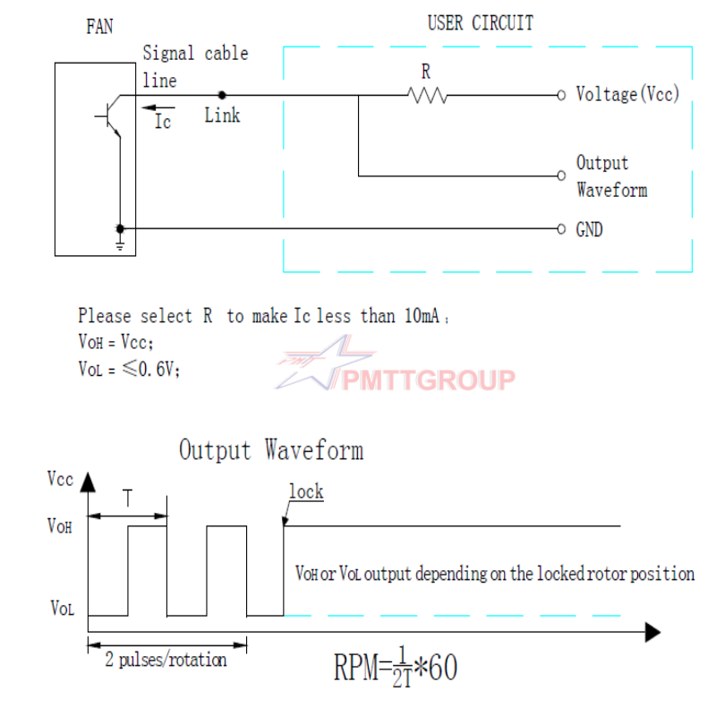
11.0. FG: TACHOMETER OUTPUT
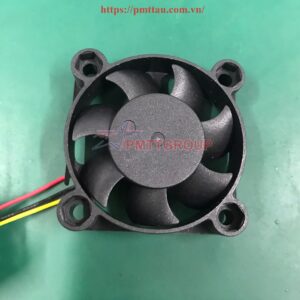
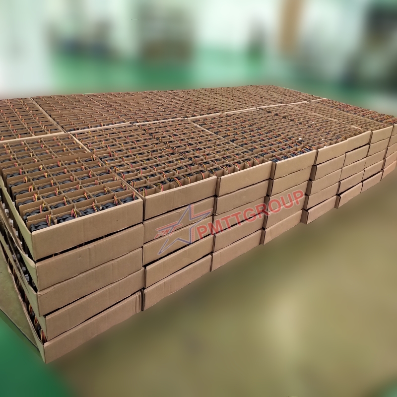
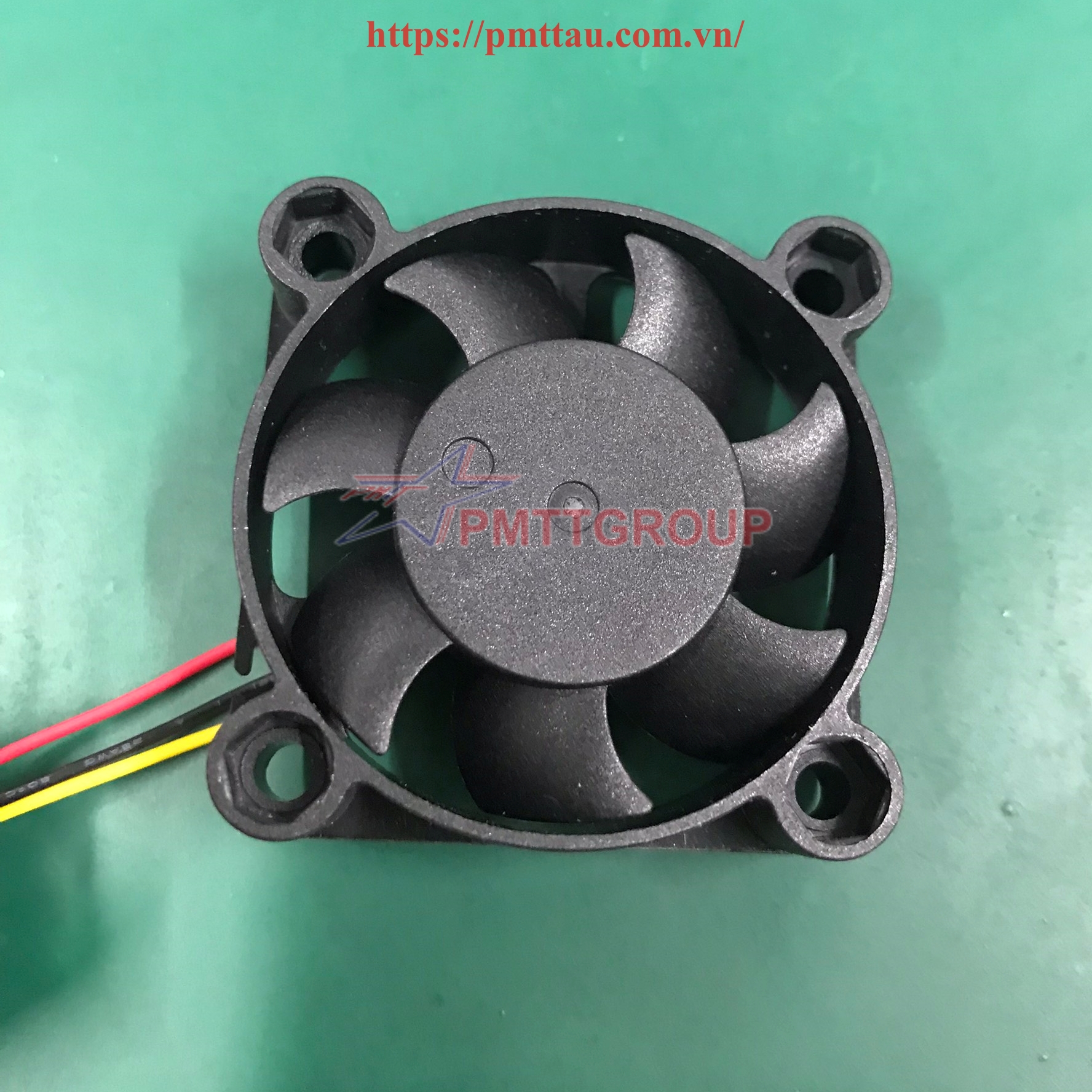
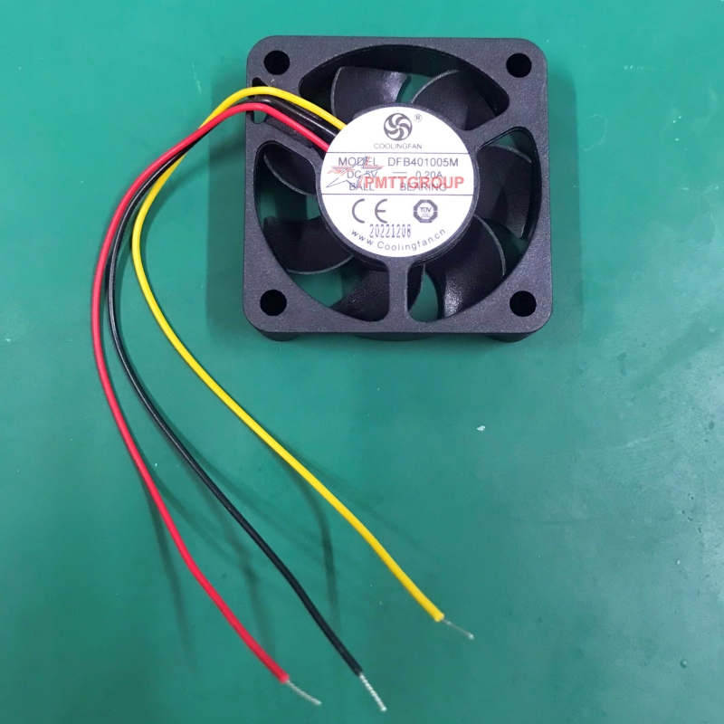
12.0. ACTUAL PRODUCT IMAGES


Reviews
There are no reviews yet.